The Aerospace History Blog - Page 17
Vertical take-off in the 1930s
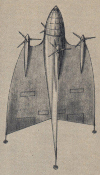
This German aircraft project from 1936/37 is probably unknown to most
people. Ewald Engler from Wilhelmshaven reported on it in a magazine
in 1955.
He wanted to improve the performance of the helicopters that were
still under development before the war. A vertical take-off and landing
aircraft seemed ideal to him. The long wings commonly used at the time
for aircraft did not allow high flight speeds. Engler carried out model
tests and came up with the wing shape shown here. In the single-
engine version, the wings were slightly twisted against the direction of
flight to compensate for the propeller torque.
He submitted his designs to the German Aviation Research Institute in
Adlershof in 1936. The institute replied in writing on June 9, 1937:
"Further development cannot be recommended, as the proposal is not
considered technically feasible."
Post 074


Posted by Uwe W. Jack


Beautiful airliner on Gran Canaria island
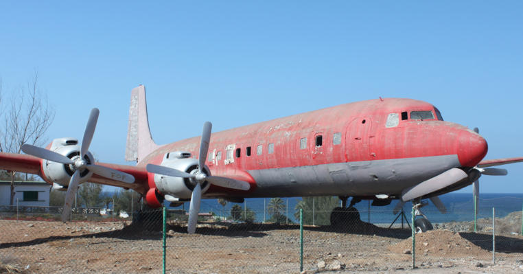
More than a dozen years ago, my wife and I went on vacation to Gran
Canaria. At the airport, in a kind of "museum", there was a Douglas DC-
7C, actually a beautiful airplane. However, the condition was pitiful.The
former EC-BBT was built in 1958 and flew for Spantax until its
retirement in 1978.
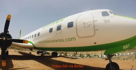
I recently learned that the Canarian regional airline Binter had stripped
the Douglas of its old paint and repainted it - thank you!
Post 073


Posted by Uwe W. Jack
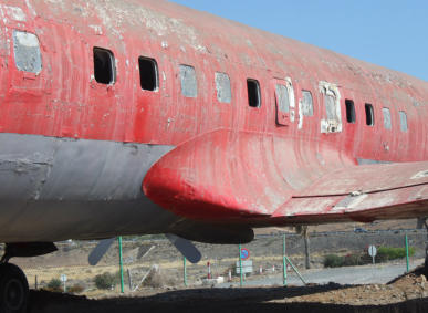
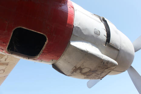
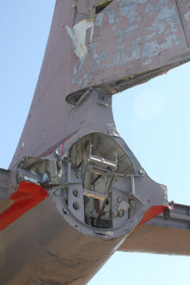
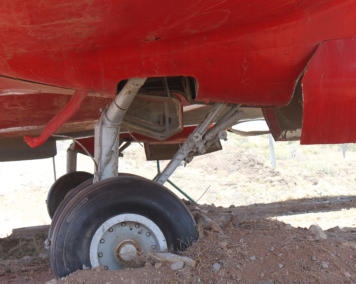
A sight of misery! The beautiful plane has almost become a wreck due to numerous layers of paint and the salty sea air.

With this campaign, the employees of Binter Air
have achieved two successes at the same time:
They have restored a valuable aircraft to its
former glory and at the same time promoted
their airline.
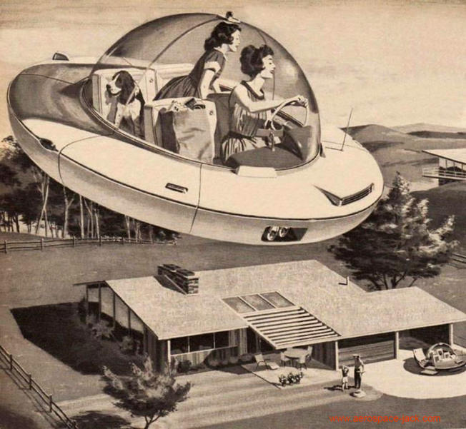
Shopping with the Flying Car
Not all dreams come true! This pretty vision from the 1950s will
probably have to wait a little longer before it is realized - what a pity!
This funny everyday scene from the future was used for an
advertisement by the American electrical industry, and readers were
promised that this would soon come true.
Post 072


Posted by Uwe W. Jack
Rocket engine of the Messerschmitt Me 163
In a facebook forum I have been asked questions regarding the thrust
levels of the engine of the rocket fighter Messerschmitt Me 163.
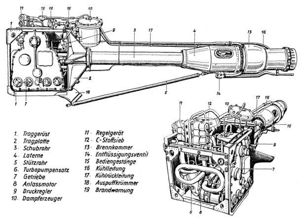
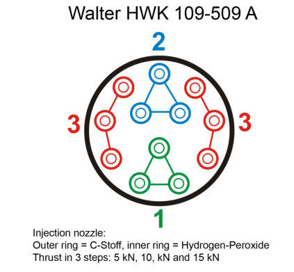
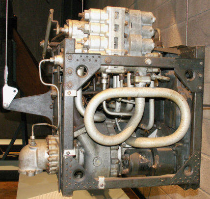
The HWK 109-509 A rocket engine can be regulated in three steps.
These steps are controlled by a rotary handle in the cockpit. A button
there starts the turbopump first. Three valves at the top of the engine
block (no. 11 in the drawing) release the fuel for each group of three
injection nozzles in the combustion chamber. The three thrust steps are
5 kN, 10 kN and 15 kN.
In the cockpit drawing, the controls for the pilot are located at numbers
13, 14, 15 and 16.
Post 071


Posted by Uwe W. Jack
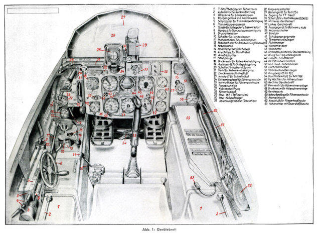
Cockpit layout of the Messerschmitt Me 163 rocket fighter.
(click to enlarge - the file may not be modified - commercial use is prohibited.)
The engine HWK 109-509 A with turbo pump system (left) and combustion chamber (right).
(click to enlarge - the file may not be modified - commercial use is prohibited.)
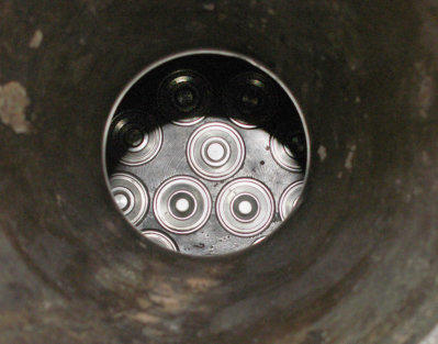
The injection nozzeles of a Me 163 rocket engine.
The turbo pump assembly with the pump at the lower end (exhaust to
the left) and the three valves for the three thrust levels at the top.


